Saturday, 24 October 2015

JC week 11: Cross guard

NB: journal entry for the Jewellery and Small object module at South bank Griffith university (QCA) to view the full journal click here

This post discusses the bending of the cross guard and riveting of the brass cross guard panels.

Bending of the cross guard

The intention is to create a bend in the cross guard so that it curves half way around the threaded blade shaft.
Step 1: bend the aluminium ( annealed) over the blade thread shaft.
Step 2: using a pair of pliers ( while the crossguard is still on the shaft: figure 1) carefully bend the cross guard so that it runs at a 90' angle.
Step 3: repeat process to other side of cross guard.
Step 4: remove the cross guard from the threaded shaft and lay on a flat surface to make sure that both sides are uniform.(figure 2 ) , gentle pressure was applied by hand to flatten the cross guard.
NOTE that annealed aluminium is very soft.

figure 1


figure 2


The three portions cross guard, woodencore handle and test blade combined to check for aestheics


Riveting brass cross guard panels


ABOVE : the two brass cross guard panels prepared earlier
Step 1: the two brass cross guard panels are bent around the handle to form a similar shape to the aluminium cross guard wings


Step 2: align the two brass panels either side of the aluminium wings (cross guard) to hold the three parts together I used 1 inch clips
Step 3:Drilling the rivet holes. The copper wire used in this project for the riveting is 1.5 mm thick, the drill bit used is the same thickness. Drill a hole through all three of the parts.


Step 4: Push the copper wire into the hole making sure that it goes all the way through


Step 5: Cut the wire so that at least 1mm is exposed either side of the join


Step 6: Using a tack hammer gently flatten either side of the wire onto a firm metal surface, I use the flat of my vice. 
Step 7: repeat this process for the other end of the cross guard


Some reshapping of the brass cross guard panels was needed but here is the finished cross guard attached to the handle. 

JC week 10 : Sword handle wooden core and first attempt paper blade

NB: journal entry for the Jewellery and Small object module at South bank Griffith university (QCA) to view the full journal click here


This post covers the creation of the wooden core (25cm long 4cm wide 2cm deep)  for the sword handle. The shape and design has been based on the feder german longsword. The intention is to create a wooden core which allows the steel rod of the sword blade and the brass tube segments. Using a length of pine timber  ( 50cm x 4cm x 2cm ) to create the wooden core.
 (BELOW : left) to be fitted 
Equipment used: Utility knife, round wood file, coarse sand paper.


ABOVE: using a vice to hold the timber in place the wooden core has been marked out , at 30cms to allow for overcuts and basic shapping of the timber has begun. 
Step 1: using the utility knife wittle away the basic shape
Step 2: using the wood file refine the shape until the brass tube segments can be inserted with the wooden core.
Step 3. Using the sandpaper, smooth the surface of the wooden core.


ABOVE: To test the fit of the brass segments, the wooden core needed to be stood upright. The fit needs to be fairly tight.


ABOVE: Finally a  horizontal channel (2mm wide ) was cut into one end for the cross guard to be inserted.  


Paper blade test


paper blade : talks about the spiritual connection, non litteral, its not a weapon for physical battle but one for spiritual battles . The blade will be made out of scriptures relating to core beliefs which have importants to me. This test is made out of regular photocopy paper

concept drawing of mold making process and final blade result
 A plaster mold is made of a sword blade.
Step 1: create a mound of sand (90cm x 15cm)  that is slightly larger than the sword blade (80cm x 5cm)

Step 2: Lay the blade down in the sand making sure that half of the blade is submerged in the sand
Step 3. Cover the blade and the sand in cling wrap, otherwise the paster will be filled with sand
Step 4. Cover the exposed blade and 2cm past its edge with 4 layers of 'plaster of paris' bandage wraps.(BELOW)


 Step 5. Once the plaster dries ( over night) gently remove the blade from the plaster of paris and brush away any sand that may have gotten into the mold. The mold is now ready.


Making the blade

Preperation:
Prepare Bond Crete 1:5 water ratio into a small bucket. For a full size blade about 1 liter of mixed bond crete will need to be used. 
Tear apporx 40 sheets of A4 paper length wise into 1 inch strips (1 inch x 29.5cm) 


Step 1: layer the mold with 4 layers of the paper strips that have been soaked in bond crete (soak for 10mins) 
Step 2: allow to dry overnight
Step 3: remove from mold (BELOW) this has now created half of the blade. 
Step 4: repeat steps 1 to 3 to create the other half of the blade


You now have two half shells of the blade, A threaded steel rod will need to be placed in one half of the mold. Along the length of the steel rod thread on 2 bolts, these will hold the blade in place. Put one bolt two inches approx. at thickest part of the blade where it connects to the cross guard. ( BELOW)


Image 1

N

Image 2
 Now cover over the entire threaded steel with two layers of paper.(BELOW) and allow to try (over night).
Once dry then twist lengths of paper ( 1inch by 29.5cm) and place them into the blade cavity, filling it level with the edge of the mold. While still wet, Place the top of the blade into the mold, closing the surface and applying gentle pressure so that the blade top bonds with the filled base.


ABOVE: again allow it to dry overnight, there will be a few tags hanging off the joined edges but these can be cleaned off with a utility knife, The finished blade is very hard due to the density of the paper and is more than strong enough for the final project.


JC week 10 : cutting and silver soldering the pommel and handle connectors

NB: journal entry for the Jewellery and Small object module at South bank Griffith university (QCA) to view the full journal click here

Cutting and silver soldering the pommel and handle separators

The following covers the creation of the handle segment separators and the cutting and soldering of the pommel segments. 


Pommel Separators

TOP: original length of strips to be used for the seperators
Middle and Bottom: Strips after being run through the press roller
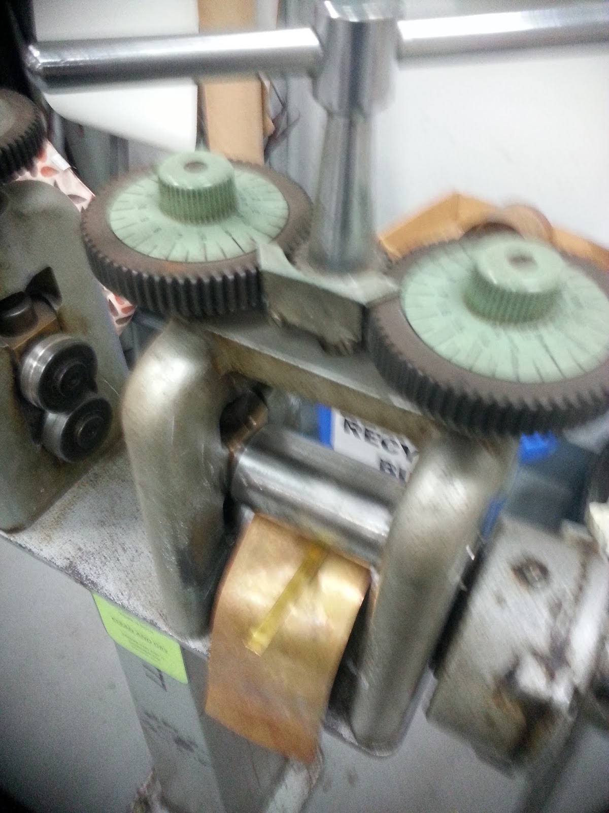
I had misscalculated the lengths of the brass strips needed for the handle segment seperators. The original length cut was 10cms, the required length was 11cms. The Handle segments had altered shape after soldering and reshapping. While not ideal, my solution was to run the seperator strips though the roller press (figure 1). This did lengthen the strips as desired, but also made the metal thinner. For this project this isnt detrimental, but not recommended practice.


figure 1


figure 2

The next step was to bend the brass strips into rings, and solder the joins. This was done using silver solder. The purpose of the separators is to 1. stop the segments of the sword handle from moving about 2. cover the tops and bottoms of each of the segments. 
To stop the separators from sliding around I soldered two strips of copper wire (2cm in length 1.5mm width) to either side of the separators (figure 2) . This proved adequate as a solution as can be seen below  (figure 3 )

figure 3

Pommel segments


The pommel (the end of the sword)  is intended to be made in two segments, the ring and the join which can be seen in the original marquette below.


 Joiner portion of the pommel :segment 1


ABOVE: the design of the joiner, seen with the paper shape to the top right, is transfered onto the brass plate. Then cut using a jewellers saw. Finally the piece when cut free is annealed and bent into a ring shape ready for soldering depicted BELOW .


This segment was then soldered, using silver solder and cleaned with citric acid

Note ALOT of filing will be needed for the circular disk to be incerted.


Circle for pommel :segment 2

ABOVE: A strip of brass , 15cm by 3.5cm was cut and annealed
ABOVE: this was then bent into a circle shape and the joining edges were soldered using silver solder


This is the result of the segment dividers, and the two pommel segments. After careful consideration, the hollow ring at the top will be revised for conceptual and aesthetic relevance as I feel that it is not suitable for this project.  

JC week 11: Channeling timber center

NB: journal entry for the Jewellery and Small object module at South bank Griffith university (QCA) to view the full journal click here

Cutting a Channel into the timber handle for the steel rod.

As the blade of the sword has a steel rod running its length the intention is to continue this length through the handle of the sword to hold the entire object together. The handle of the sword has a timber core, which is 25cms in length and needs a hollow core which is 3/8 inchs wide to accomodate the threaded steel rod.


This is the timber sword handle core held in a vice, note that either side of the timber there are pieces of timber, this is to reduce damage caused by the vice, without it the vice jaws would leave bruising and scoring on the surface.

ABOVE: The sides of the channel were cut using a regular wood saw. Making sure to cut on the inside of the marked line for the 3/8 inch channel and cutting only halfway through the timber of the sword handle core.

ABOVE: The next step was to carefully chisel the channel, making sure that I cut at a 45' angle and gently levering the timber free, remember to always cut across the grain in this stage. The intention is to remove all of the timber in the center of the two lines running the length of the image above

ABOVE: once the bulk of the timber has been remove now chisel the center going WITH the grain, this will make for a clean cut channel and reduce unwanted splintering

ABOVE: continue this process until a channel has been carved halfway (10mm testing with a depth guage for consistancy)


ABOVE: The next step is to use a rounded file and file out the rest of the channel, so that it will be a tight fit for the steel rod/sword blade core

ABOVE: NOTE in the image above, the channel for the cross guard has been filed wider to acommodate for the curve (pictured BELOW. 

Tuesday, 13 October 2015

JC week 9 silver soldering brass with a propane torch

NB: journal entry for the Jewellery and Small object module at South bank Griffith university (QCA) to view the full journal click here


silver soldering brass with a propane torch


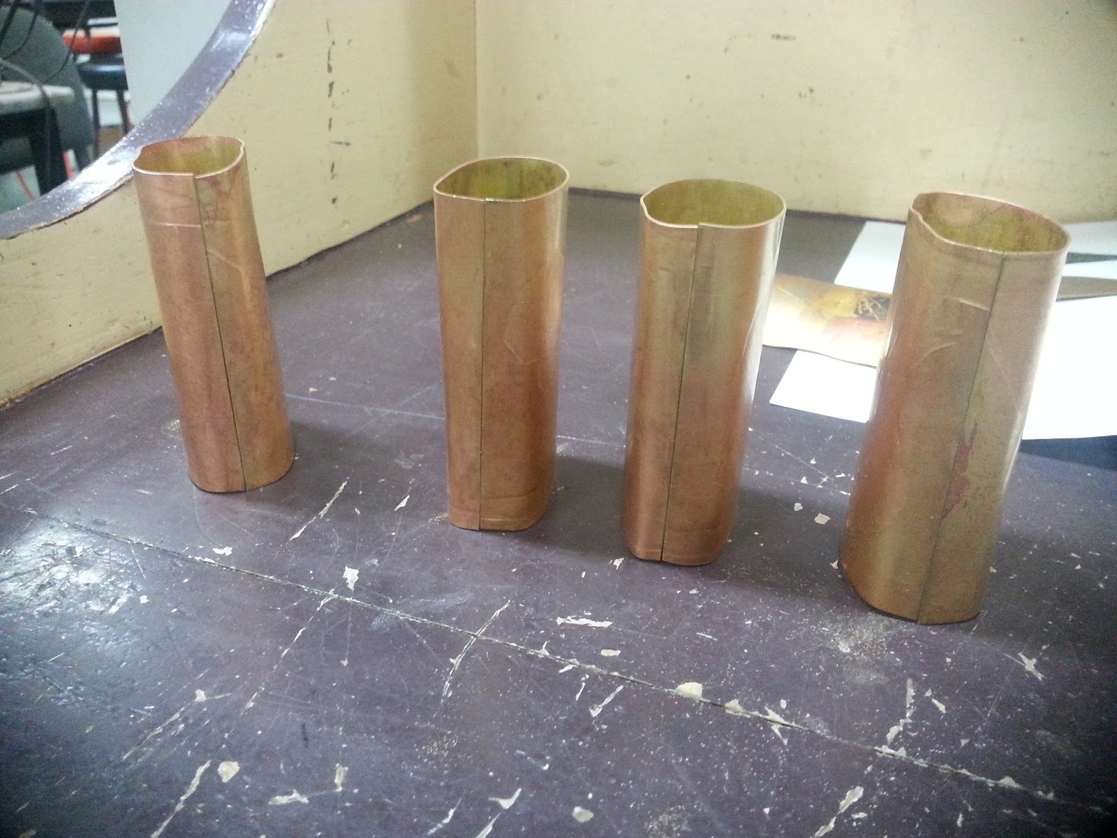
ABOVE: these are the brass cylinders that are to be soldered, they are 10cm circumference by 11cm high

Preparation is important for soldering, make sure you have everything you need before you start especially EYE PROTECTION. 


ABOVE: make sure that you have sufficient silver solder bits cut.  Medium silver solder will be used for added strenth and the lenths will be cut at approx 1mm. I cut enough for 4 pieces of solder for each cylinder and a few just incase they fall off, which  happens.


ABOVE: pictured here are EYE PROTECTION,  the silver solder pieces are in the piece or paper to reduce loss and make picking up easaier, a Titanium pick (bottom center) this is needed as it can handle the high heat and move the solder around , fire bricks


ABOVE : the use of the fire bricks is to stop the brass cylinder from falling over while heating,  This also demonstrates the placement of the silver solder pieces. NOTE after this photo was taken I took the silver solder off the brass cylinder, and applied a coat of flux paste to the join, this helps in  placing the silver solder and acting as a guage of how hot the brass gets (turning clear  indicates annealing temperature)
To solder the brass, apply heat with a propane torch, the idea is not to focus on the silver solder pieces directly, but instead to focus on heating the metal directly around .
I discovered very quickly that such a large piece of brass was difficult to solder  taking a VERY long time ( 55mins approx ) and required the assistance of a second propane torch to get the solder to melt and bond effectively. Sadly some of the joins were ineffective due to lack of sufficient heat. 


ABOVE : finally once the solder has air cooled and been quenched ( placed in a dish of cold water) the brass can be placed in a citric acid bath for 5 minutes and cleaned with a medium copper wire brush.


Other class activities


After soldering the brass cylinders I took the opportunity to anneal the cross guard pieces for the sword in preperation for the next step

JC week 9 preparation for silver soldering brass sword handle


NB: journal entry for the Jewellery and Small object module at South bank Griffith university (QCA) to view the full journal click here

Preparation for silver soldering brass sword handle

To be able to silver solder brass you need to have a tight, clean join between the two surfaces.
The intention is to solder four brass cylinders that are 11cm high by 10cm in circumference.
For silver soldering with a propane torch this is a large surface area to heat so the cleanest possible join will be needed.
Also note that these cylinders have an embossed surface

Embossed brass sheets that are to be made into cylinders and soldered for the sword handle


First using a rounded timber length, the brass sheets were bent around it making a basic cylinder shape

The edges that are to be soldered need to be bent so that they are parallel to one another, this was achieved by placing the basic cylinder shape over a thin strip of timber


While still on the timber strip I shaped the edges carefully with a rubber mallet, taking care not to damage the embossing on the brass surface. This process was repeated on all of the cylinders.


as you can see while the edges are now running parallel but there is quite a large gap,  I carefully bent the join past its connection point both front and back, the idea here is to use the tension of the metal itself to create a tight join.
\

The result of the before mentioned method creates a tight join, note the top is not level, for the purpose of soldering this is not important as this occured when the metal was run through the press roller to create the embossing.


The brass cylinders are now ready to be soldered.

Also note that the cylinders do not need to be perfectly shaped at this point. The heating process when soldering can/ cause distortion in the metal and once soldered the cylinders can be reshapped