 |
| Shape inspiration for the clockwork key IMAGE SOURCE : http://www.supremeplumb.com/cgi-bin/DMdatabase.cgi?action=/Shop/Plumbing_Fittings/Central_Heating_Accessories.txt&item=00011 |
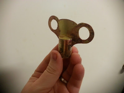
As a replacement to the circle at the end of the pommel ( which was to represent my beliefs in reality ) I have decided to create a clockwork key.
 |
| Figure 1 |
Drawing the design
The clockwork key was made out three annealed brass panels (panel(1) :7cm x 4cm panel(2) 8cm x 4cm and panel(3) 5cm x 2.5cm) . The smaller of the two was rolled into a tube, which will become the base of the clockwork key ( pictured in top center of Figure 2). Panel(1) was used for making the top of the clock work winder. It was place over a piece of snowden paper and marked out. Using a compass I maked out the basic design for the clock work key top. (Figure 1)
 |
| Figure 2 |
BELOW: The paper design was then cutout , and using blu tac, attached to the brass panel ( panel(1)). Using an 8B graphite pencil the design was traced around, and sealed using fixitive spray, this reduces smudging of the lines.
BELOW: Using the Jewelers saw the deisgn was carefully cutout.
Capping the end of the clockwork key base
BELOW: Placement of the brass tube onto a larger brass plate before silver soldering.
BELOW: Note when soldering the larger surface area of the plate will require heating for longer than the join closest to the edge. Placement of the solder is critical to making sure that it is joined all the way around, at first i had intended to place the solder on the inside of the tube and heat from the outside, its easier to place it around the outside, and for a piece this side placing a piece of solder every 7mm approx. is sufficient.
BELOW: Once soldered(silver) the tube can be cut free from the base plate
BELOW: The final step is to cut a slot in the brass tube for the clockwork top to be inserted into. This was done using a dremmel and a 1mm cutting disk. A slot was cut directly through the center and 1cm down either side of the tube.
Note in the image there is a bent piece of brass on the table next to the cutting dist (center bottom). It is always prudent when making a precision join that you test out the cutting disk first. Three attempts were made with different thickness disks before the correct width was found.BELOW: Once the burrs have been cleaned out of the slot, the top and tube of the clock work key can be joined together. ( hand in photo for scale)
The final process will be to insert the 3/8 inch threads into the tube of the key, this portion of the project will be holding the entire sword together.
 |


No comments:
Post a Comment